Live IO
Introduction
The delay finder’s role is to determine the total delay of the signal path, from source to response. Note that this excludes any delays induced by your soundcard and DAW, as these should be compensated for and equivalent to zero as explained before. Here we are only concerned with the time taken by sound-pressure waves to travel the distance from loudspeakers to the measurement microphone placed at the listener position.
This figure must be determined with sample accuracy in order to establish proper transfer function and impulse response measurements. In a sound installation context, computing precise time-delay is crucial to align multiple speakers and transducers properly, as to minimize comb-filtering artifacts.
Basic operation
Compute the delay
Press the  button to find the delay using the most recent incoming audio. The resulting figure is displayed almost instantly as a:
- Delay in samples (smp).
- Distance in meters (m) or Imperial feet (ft.) depending on whether Metric system is enabled.
- Delay in milliseconds (ms).
Compensate the delay
Pressing the  button activates a delay line in the source signal path to compensate for the currently displayed delay value, effectively time-aligning source and response signals. Pressing again deactivates the delay line, which allows for quick comparison between uncompensated and compensated signal paths.
Fine-tune manually
If necessary, you can manually adjust the delay figure using either of these methods:
- Direct keyboard numeric value entry as time or distance figure.
- Increment / decrement by clicking the +/- icons.
- Increment / decrement using the +/- numeric keys.
Perform a new measurement
Press the button again to perform a new measurement. This will overwrite any previous value.
Notes
Max. delay time and room/venue size
The maximum measurable delay time is adjustable in the settings. Attempting to measure a delay greater than this will inevitably lead to corrupt measurements. The default setting is 1s, which should cover the vast majority of real-world situations, since it covers a distance of 330 meters.
Ensure stable conditions while performing a measurement
You should ensure both source and response signals have reached stability before attempting measurement. In particular, do not stop or start the audio, change the volume or any other parameter just before or during measurement. This would invalidate the measurement and you would have to start again.
Limitations
Please note there are many unknowns in play when determining the optimum delay figure. While we did our best to make this tool as robust and accurate as possible, as with all automatic procedures there is always a possibility that it will fail. In this case you should repeat the process or resort to manual adjustment until you get satisfactory results.
Multiple paths
The major assumption behind delay compensation is that there is a main direct path from source to listener. In a very reverberant or complex-shaped acoustic space, this obviously does not apply anymore. This is where acoustics expertise and trial-and-error comes into play, in order to attain the best compromise.
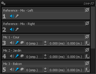
User interface and controls
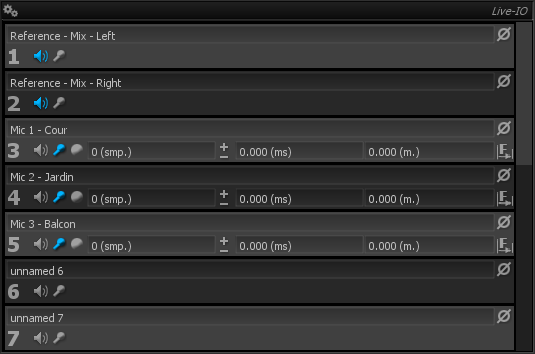
Name
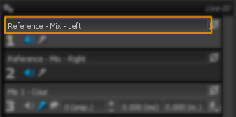
Allows to define a custom name for each channel. This is a global name; saved and restored with the preset but not directly related to the Hardware I/O Interface. As this, it will be consistent even if you switch the Hardware I/O Interface or switch to connect to a SampleGrabber Principle of operation.
Ref
The  button toggles whether the corresponding channel should be used as a reference signal.
Multiple channels can be used as reference, in which case a mono-sum of these channels is used as the internal reference signal.
Mic
The  button toggles whether the corresponding channel should be used as a microphone input signal, which is used to capture the response of the system.
Multiple channels can be used as microphone input, in which case a mono-sum of these channels is used as the internal microphone signal.
Phase invert
The  toggles phase inversion of the selected channel on and off. This can be used to compensate another known phase inversion somewhere else in the analog signal chain.
On/Off
The button toggles delay compensation on and off. When the correct delay has been determined, engage this button to insert a delay line in the reference channel, to align reference and measured signals, and get correct transfer function and impulse response.
On/Off delay button appears only on channels toggled as microphone>
Delay value
The delay value is displayed simultaneously as:
- A number of samples (at the current sampling rate).
- A time delay, in milliseconds.
- A distance, in meters or feet.
You can manually adjust any of these values, using either keyboard input or fine increments with the up and down arrows; the two other values will change accordingly.
Please note precision of the distance value depends on correctness of the temperature value inserted in the main setup. In a concert hall with an audience present, there will probably important temperature variations, so this value should only be seen as a rough measure.
Lastly, remember the delay value in samples is the master value, from which others are derived.
Delay values appears only on channels toggled as microphone>
Find
Clicking the button starts a new delay value computation. Previous values, whether computed using the delay finder or entered by hand, will be erased. The algorithm accumulates a certain amount of incoming signal before the actual computation is actually performed, to ensure the delay is always computed using the most current audio.
Find Delay appears only on channels toggled as microphone>
Progress
An informational text showing the progress of the computation is shown when the delay find button is clicked, as well any error potentially encountered.
Setup
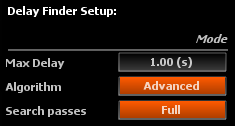
Delay finder setup options.
Max delay
Sets the maximum delay that can be computed. The default is 1 second, which equates to a maximum distance between microphone and speakers of roughly 300 meters, and should be large enough for most practical applications. You can decrease this value as this minimizes the possibility of false readings.
Algorithm
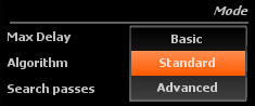
Selects between three different delay finding algorithms:
- Basic: lowest CPU load, less robust to noise and interference.
- Standard: medium CPU load, the default.
- Advanced: heavy CPU load, can help in very noisy environments.
In the rare case where the standard method fails in your particular environment, you should try other methods.
Search passes
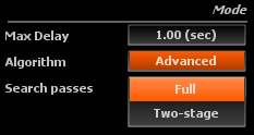
The delay can be set to work in one or two passes:
- Full (default): one search pass covering all possible values.
- Two-stage: first pass to determine a rough delay value, followed by a second to refine the reading.
Two-stage delay finding can improve accuracy in the context of an environment with heavy multiple reflections.