Initial Hardware and Software Setup
Throughout this documentation, we will refer to the measured signal processing chain as the system (sometimes called device under test in electronics literature). This system input is fed with a source signal, which produces a response signal at its output(s). Both source and response are recorded and monitored by the analyzer, from which several measurement curves are produced.
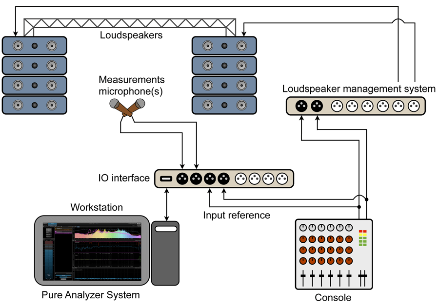
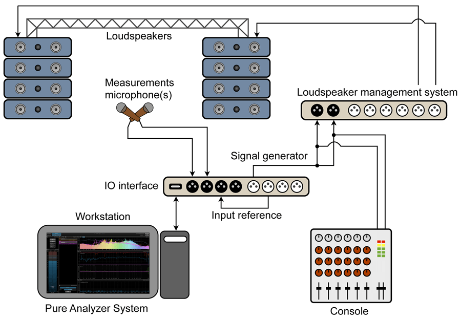
The first step is, therefore, to set up the measurement chain. In cases where an outboard or plugin device’s characteristics are to be measured, this is just a matter of routing the inputs and outputs in your DAW.
If you’re measuring the acoustic response of a physical space, you’ll need to place at least one microphone at the preferred listening position to record the response. The source can either be picked up directly at the DAW output or recorded with a second microphone placed in front of the loudspeaker(s), depending on whether you want to include the loudspeaker’s influence or not in the measurement.
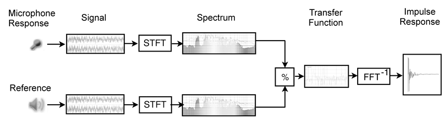
System analysis overall principle.
Practical considerations for capturing measurement signals
At first glance, an audio signal chain is very much like a series of black boxes. As an audio engineer, you can trust your ears and the manufacturer’s data sheets to assess the effects this chain has on the incoming audio. In a variety of cases, however, this is either simply impractical, not possible or not precise enough. Such situations include live sound setups, recording setups, etc., where unknown factors such as the venue’s or studio’s acoustic response are a crucial part of the chain.
It is therefore necessary to resort to scientific measurement procedures and tools to obtain precise, trustworthy and reproducible results. The main tools at your disposal for this purpose are transferring curves and impulse response measurements, which are especially designed for this task.
As with any measurement instrument, it is important to have a good grasp of its mode of operation as well as any possible limitations in order to use it most efficiently. Some knowledge of acoustic principles and notions of signal processing are naturally required as well. While this manual tries to cover most typical use cases and point out common dos and don’ts, it obviously cannot replace either a good textbook or practical experience.
Use a measurement microphone
The goal here is to take the measurement chain out of the equation, so only specially designed microphones that exhibit a flat curve, minimal coloration, lowest noise and distortion should be used.
Choose a neutral preamplifier and calibrate it accurately
For the same reasons, select the most neutral preamplifier and A/D D/A convertors you have at your disposal. It is especially important to be able to set accurate and reproducible gain, linear and flat responses. Take special care that the signal is not so hot as to clip or distort the preamplifier input stages, as this would distort the measurements accordingly and induce you into error.
Maximize signal-to-noise ratio
When measuring an acoustic system, raise up the volume as high as practical for maximal signal-to-noise ratio, and try to minimize any spurious acoustic noises such as footsteps and conversation. As always, the goal is to set the test signal as high as possible above the noise floor while ensuring all devices still operate in their linear region. Finally, make sure the microphone is firmly held in position and acoustically decoupled from the floor.
In a live concert context, especially with the audience present, using a noise signal is not practical. In this case, you can still perform measurements using a music signal, but the measurements will be less accurate as the signal isn’t known in advance and does not necessarily contain all frequencies like noise does.
Measurement setup
Test signals
FLUX:: MiRA is designed to cover the broadest range of practical use cases, and does not impose a limitation on the measurement signal used.
Traditionally, transfer curve and impulse response measurements are performed by feeding a specially designed test signal into the system, the most commonly employed being pink and white noise and swept sines. While these types of signals are those that give the best and most accurate results, with each having its own strengths and weaknesses, they do prohibit the measurement of a system in the context of a live system with the audience present.
Performing measurements using a live music signal allows the engineer to fine-tune the system settings to compensate for changing conditions, such as the effect of the crowd on acoustic reflections and damping, varying temperature and humidity, etc.
Although less pleasing to the ear, we do, however, recommend using a noise test signal whenever possible, at least as a starting point.
You are free to use any kind of test signal generator, outboard or plugin, provided you trust it being reliable and easy to use. A selection of plugins suitable for this task is shown in the chart below.
While FLUX:: MiRA does not impose any limitation on the test signal used, we recommend using the integrated Signal generator Signal generator, which has been especially designed for this task. We conducted thorough tests on a wide panel of signal generators available as plugins or integrated into DAW software and found that many do not meet the requirements for performing accurate and reliable measurements.
Choosing a system tuning layout
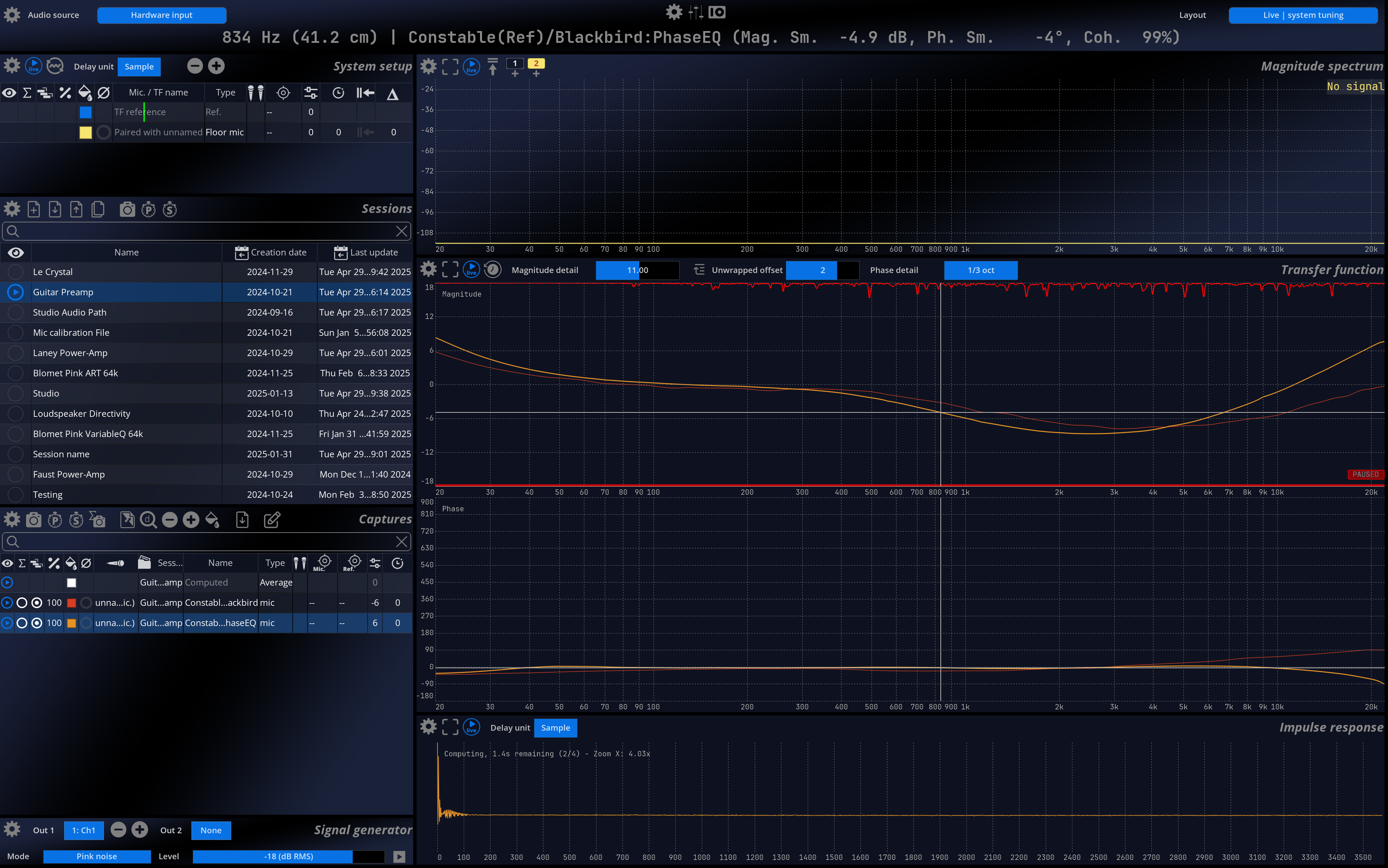
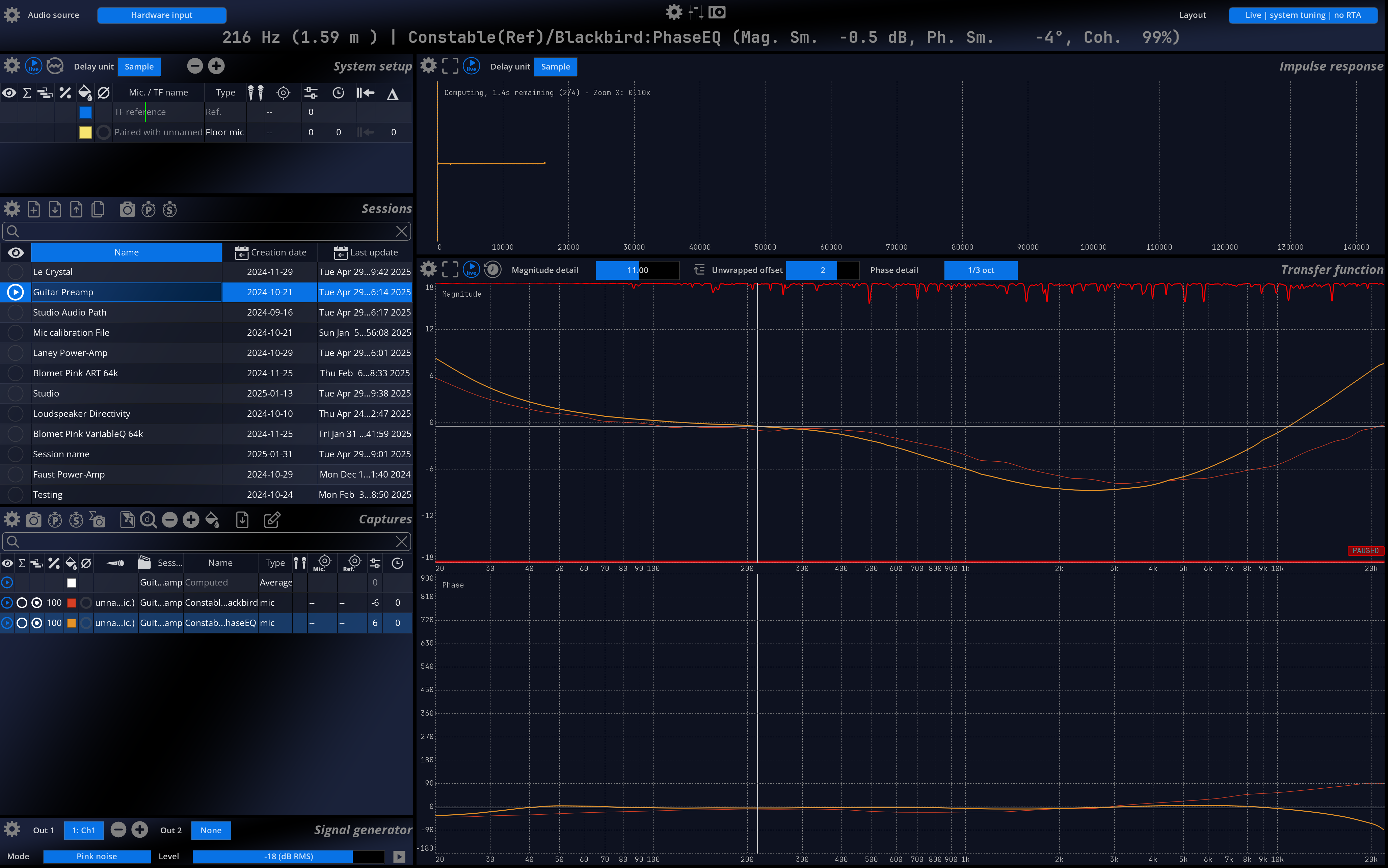
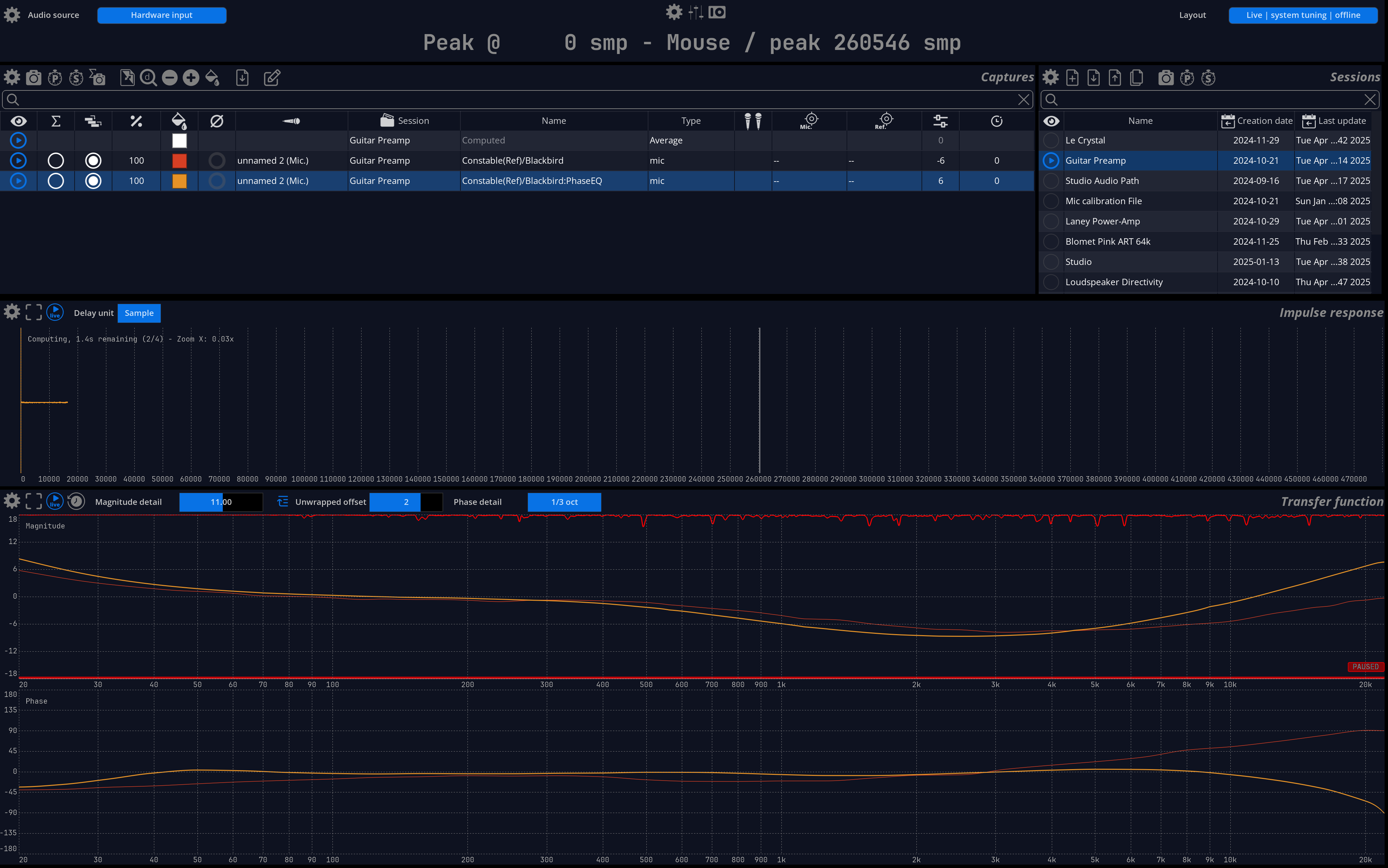
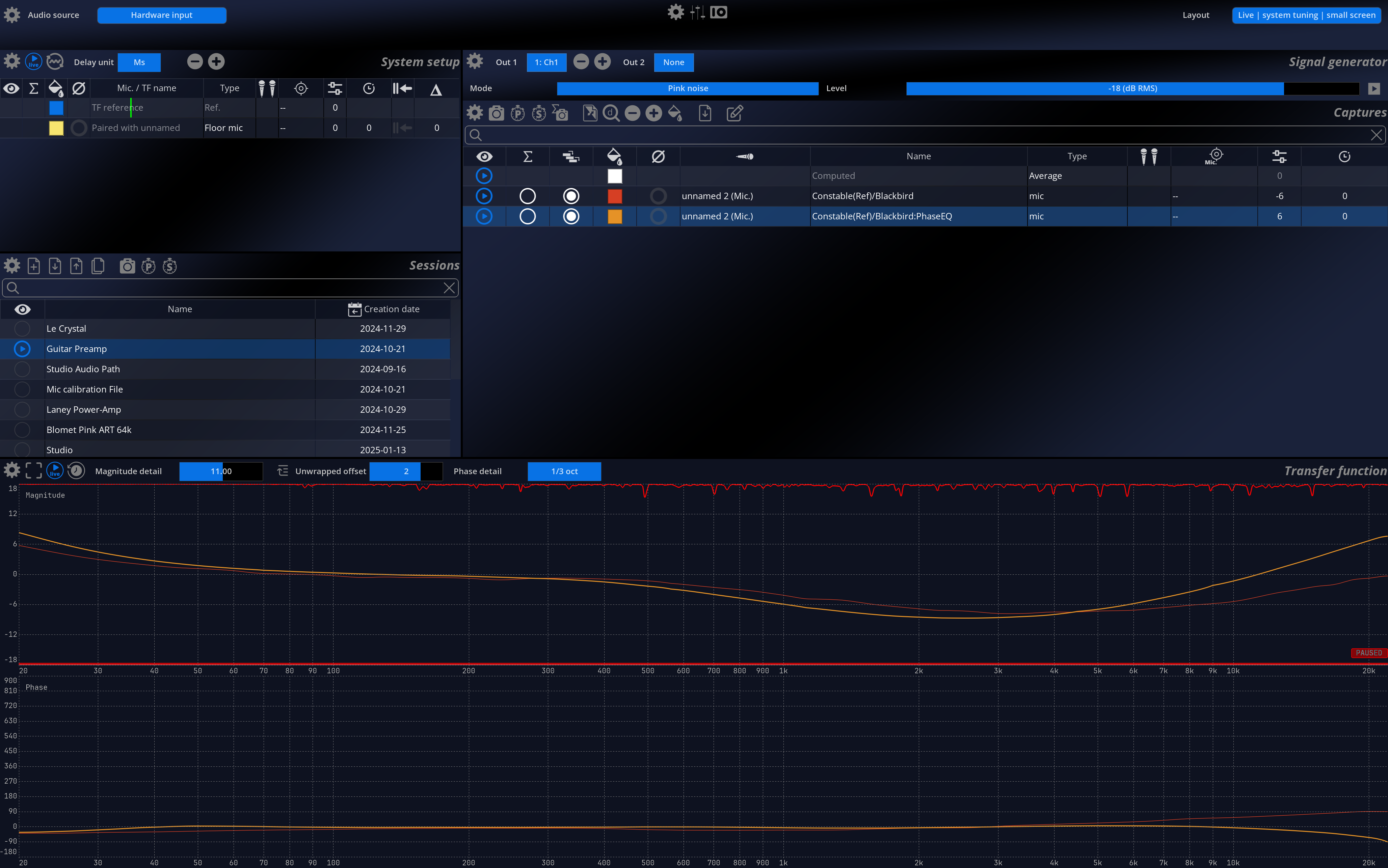
Once your hardware is well setup, you will have to select an appropriate layout (or build one!) for system tuning. MiRA ships with for different layouts for system tuning:
- “System Tuning”
- “System Tuning - No RTA”
- “System Tuning - Offline”
- “System Tuning - Small screen”
All these layouts share this common scopes dedicated to system tuning: the system setup, the capture and session management and the transfer function. The names of each layout should gives you a clear enough indication for you to make an appropriate selection.
Measurement Acquisition - Practical Consideration
When using MiRA for system tuning, all the incoming audio is stored in a circular buffer. A circular buffer is a fancy way of saying that, once the buffer is filled, we start writing at its beginning again. All the scopes related to the system tuning (transfer function and impulse response) are driven by this circular buffer.
By default, this buffer holds the last five seconds of audio. You can change its length in the preferences of the “System Setup” scope, under the name “History Time”.
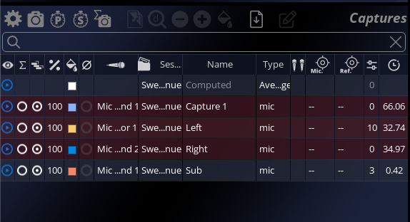
When we perform a capture, the current state of the circular buffer is stored in permanent memory. This allows us to perform recomputation, without ever having to reacquire the data from the audio system itself.
Auto-Pause Feature
MiRA uses an auto-pause function that prevents the update of the circular buffer if the signal on the reference channel is below a certain threshold. In practice, this means that you can send a signal to your system, monitor the curves in real time and store them in a capture several seconds later as long as the reference level has not risen above the detection threshold.
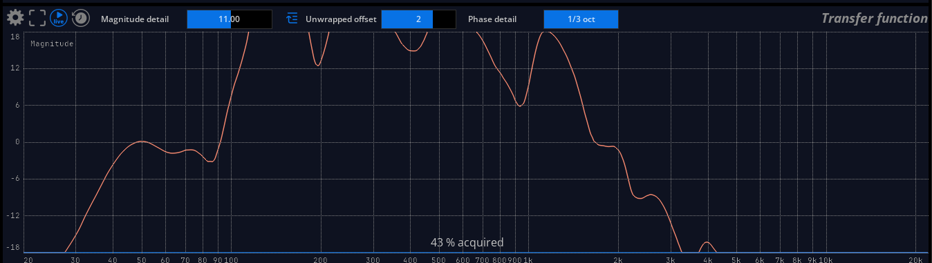
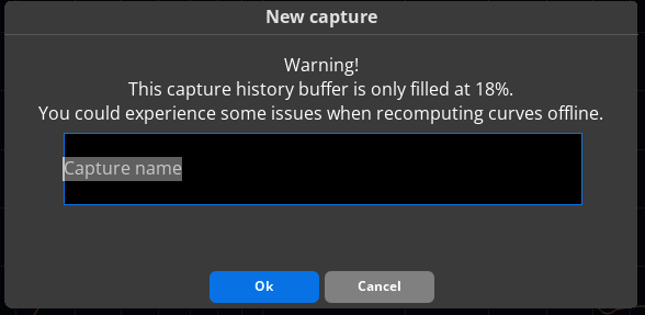
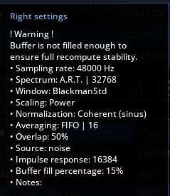
The Auto-Pause system also means that, in certain conditions, the buffer acquired in a capture could be incomplete. If the buffer is not at least filled at 50%, warnings will be displayed.