IO Configuration
The MiRA application supports up to 24 input channels. There are two main usages for this audio stream:
- Feed the RTA system; also called input reference (red parameters and information)
- Feed the capture system; also called TF input (green parameters and information)
The capture system is only available in MiRA Live version
Each audio channel is shared by the RTA system and by the capture system. This flexibility allows to handle a wide variety of use cases, from basic ones to the most complex ones.
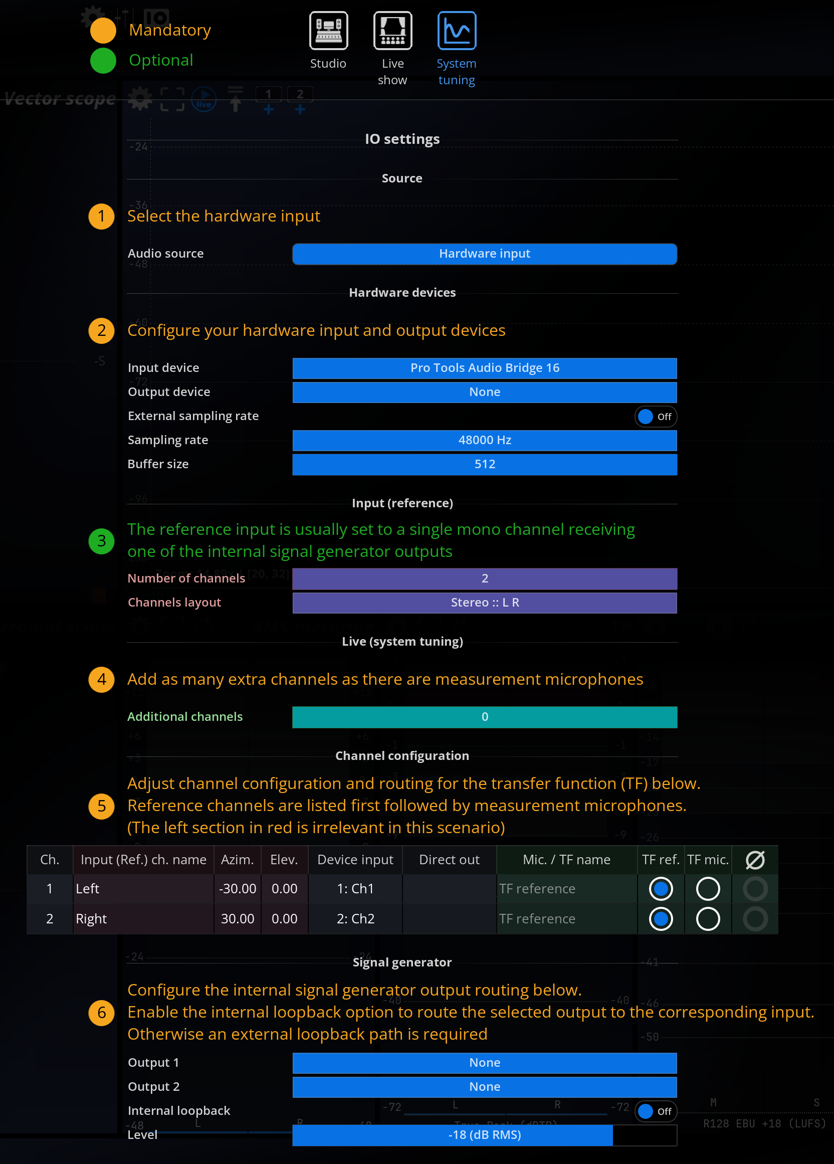
Helper toolbar
At the top of the IO setup page, there is a toolbar containing three buttons. Each button corresponds to a different typical use case of MiRA:
- Studio
- Live show
- System tuning
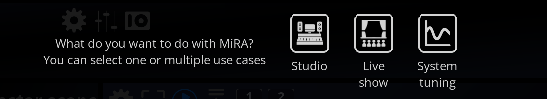
Clicking on one or several buttons displays additional text aiming at helping you with the making the right IO setup for your current usage of MiRA.
These guidelines are displayed in two colors :
- Orange to indicate mandatory settings to take care of.
- Green to indicate optional settings.
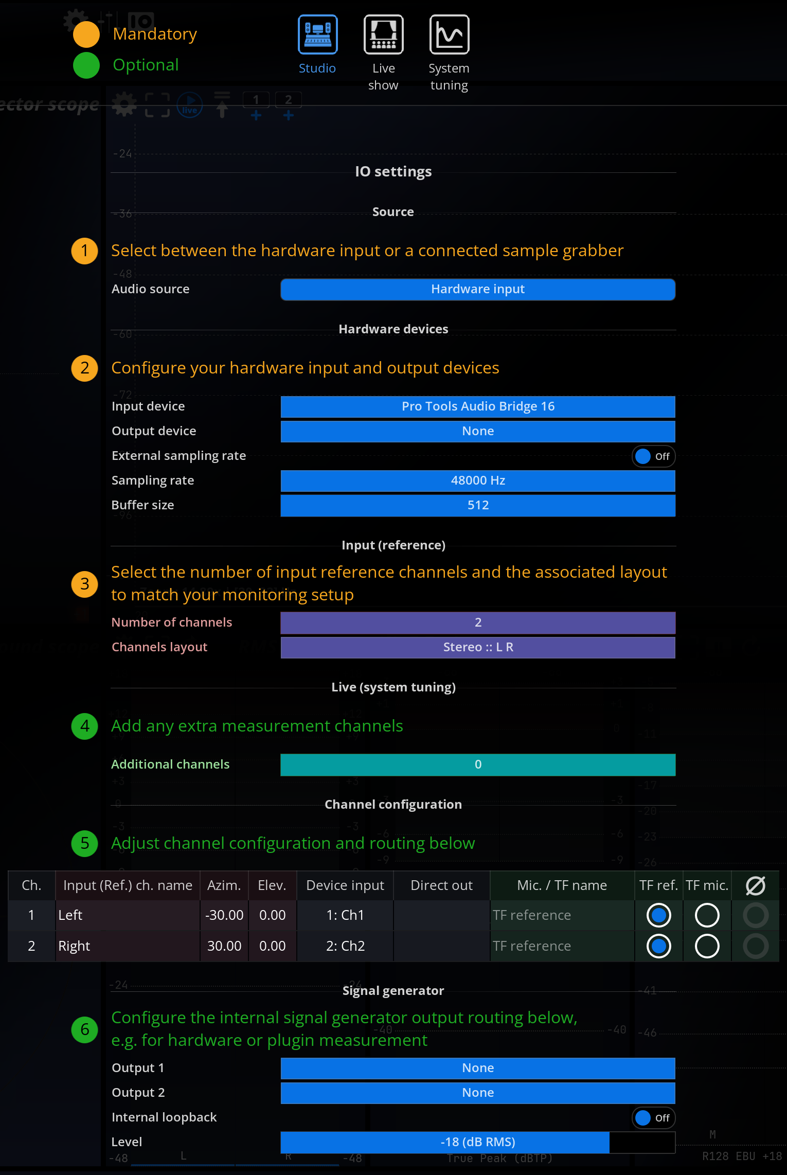
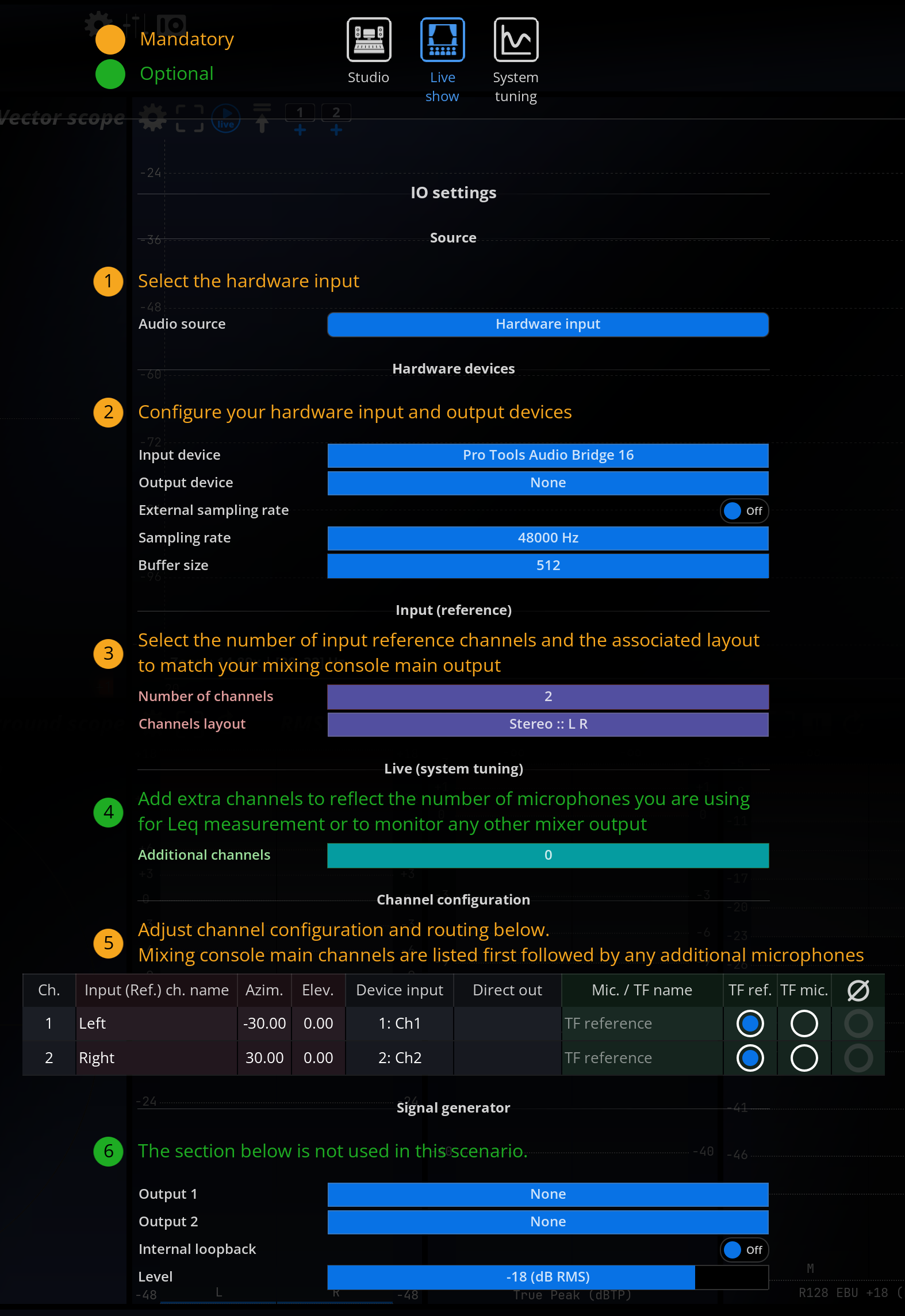
Once you have selected the right use case, just follow the indication from top to bottom to create a coherent IO setup.
Several use case buttons can be active at the same time if you plan on using MiRA in a more complex workflow. If you are beginning with the application, we encourage you to first start with one use case at the time before going to a more complicated setup.
Source
Audio source
Audio source allows you to select which source to use as input. Depending on your current configuration and settings, this will include:
- Available SampleGrabber instance(s), either local or remote.
- Available hardware device(s), if one or several sound cards are present on the host system, and the corresponding device has been selected in the Hardware IO configuration dialog.
Hardware devices
Input and output devices
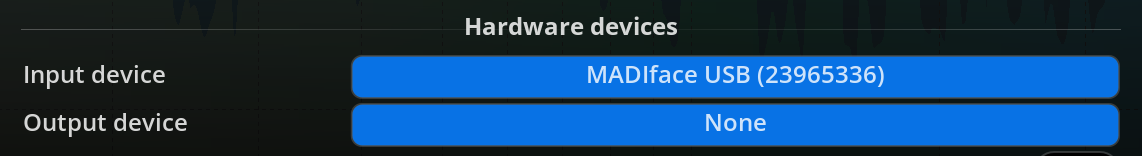
FLUX:: MiRA allows for different input and output devices. The following sections describe the available options.
This setting lets you choose amongst a selection of devices, depending on your particular hardware configuration.
None
This turns off hardware input and output altogether. This is the recommended choice if you do not want to take advantage of MiRA’s built-in audio capabilities, for example if you’re working with a SampleGrabber inside a DAW. With some sound cards that aren’t multi-client capable - meaning only one program can access it at once - disabling I/O is necessary to continue using another program simultaneously.
Your sound card
Any installed sound card(s) will be listed here. Under Windows, it might appear several times, in which case be sure to select the native ASIO driver for performance, not an emulated driver which be labeled something like ASIO DirectX Full Duplex Driver, Generic Low Latency ASIO Driver or similar.
External sampling rate
Allows the Flux:: MiRA to follow the sample rate settings of the attached audio interface.
Sampling rate
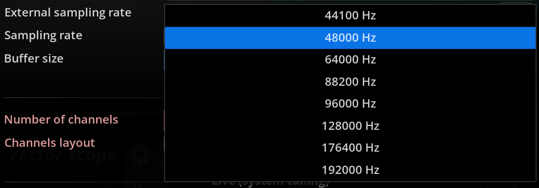
Sets the sampling rate used internally by the application. When a hardware device is selected, be sure to match this to the sampling rate set in the application panel of your sound card control panel. We deliberately chose not to employ resampling, which, in our opinion, has no place in a measurement instrument. Instead, we generally advise you to set your sound card’s sampling rate to 44.1k or 48k, which covers the entire audio hearing range (20-20kHz). Increasing the sampling rate above these values increases the processing power required to carry out the computations without any benefit for most practical applications.
Buffer size
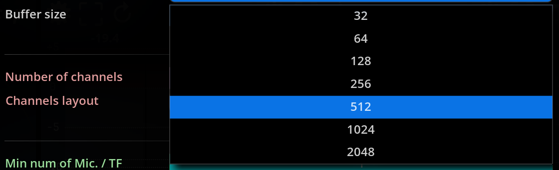
Displays the current sound card I/O buffer size. Depending on your sound card, you might be able to change this to a different value directly in FLUX:: MiRA without opening its control panel beforehand. Smaller buffer sizes lead to a shorter latency between incoming audio, display updates, and audio output. This setting is certainly not as crucial as in the context of live sound processing, so there is no need to go down to extremely small values here, as this only increases the system load without offering any practical advantage.
Keep in mind a display refresh rate of 60Hz means one frame lasts for approx. 16ms, which is a bit longer than one 512 buffer at 44.1kHz, so the display will always lag less than one frame after the audio with such a setting.
Input (Reference)
Number of channels
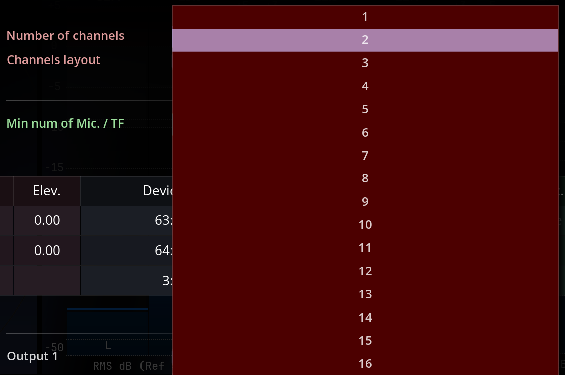
Selects the maximum number of channels to be used by the application, or equivalently the number of channels in the application I/O bus. You should set this according to the source material format you want to analyze and visualize. This determines notably how many real-time curves are displayed in the Spectrum analyzer Presentation view, whether the Surround scope Usage is displayed, etc.
FLUX:: MiRA supports up to 24 channels of audio.
Channel layout
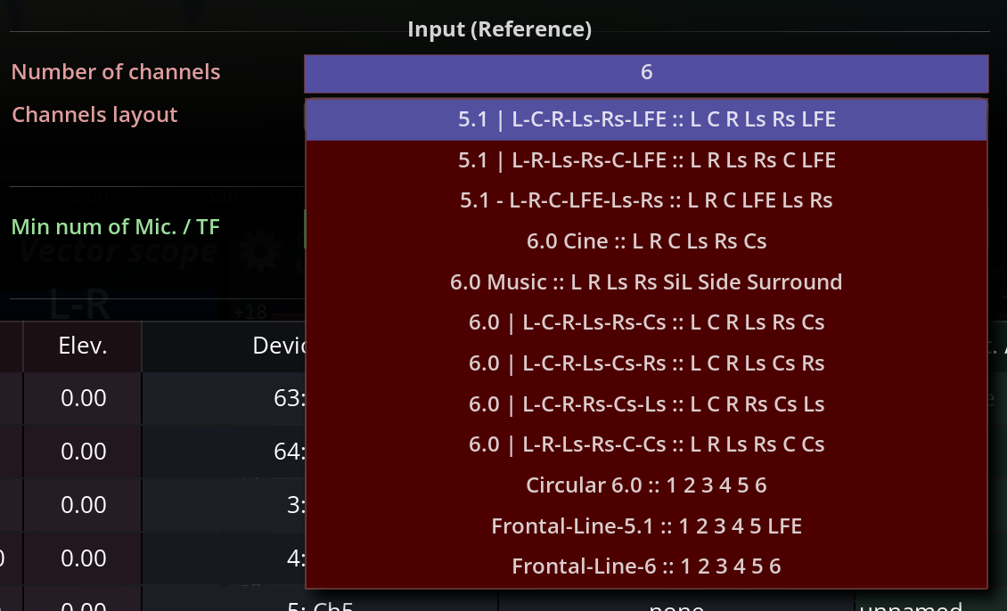
Choose the channel layout for the reference input stream. When using the SampleGrabber plugin our SPAT Revolution (SamplePush technology) the Channel Layout for Input Reference is communicated directly. For hardware input setups, MiRA is shipped with a great collection of speaker layouts that should cover all your needs as long as you are working with a “standardized” speaker layout (such as Dolby or IUT ones, for example).
It is very important to make sure that the audio streams serving as reference match exactly the channel layout specified in MiRA. Otherwise, it can lead to wrong loudness metering measurements.
If custom speaker layouts are needed, MiRA can import .ioconfig files generated from our spatialization engine SPAT Revolution. The import action is located in the File>Import IO configs submenu. All imported IO configurations are stored in the FLUX:: IO config folder, located at /Users/user_name/Library/Application Support/FLUX/IOConfigs on macOS and at C:\User\/...\AppData\Local\FLUX\IOConfigs on Windows.
Live (system tuning)
Additional channels
Defines how many input channels are fed to the capture engine.
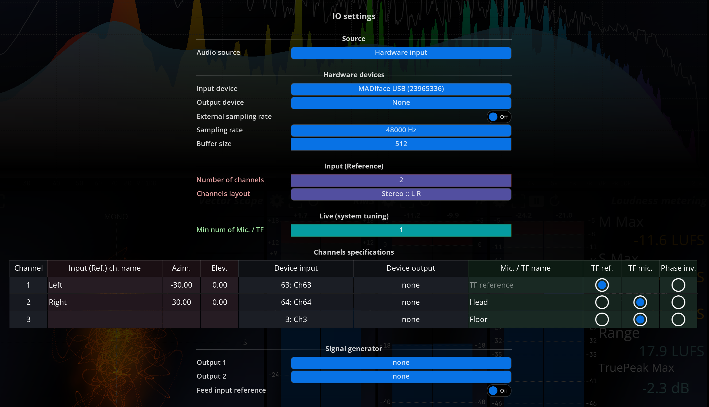
Channel specification
The channel specification table allows to specify options per channel:
- The name of the channel - display only
- The position (Azimuth, Elevation) - display only
- The routing (regarding the input and output device) - display only
- The name in the transfer function window
- Define whether the channel is used as a reference or a microphone channel in the transfer function window.
- Phase inversion
This table is shared between the real-time mode and the transfer function mode of the application. Information relative to the input reference is independent from the information relative to the transfer function measurement tools and the other way around.
Signal generator
Output
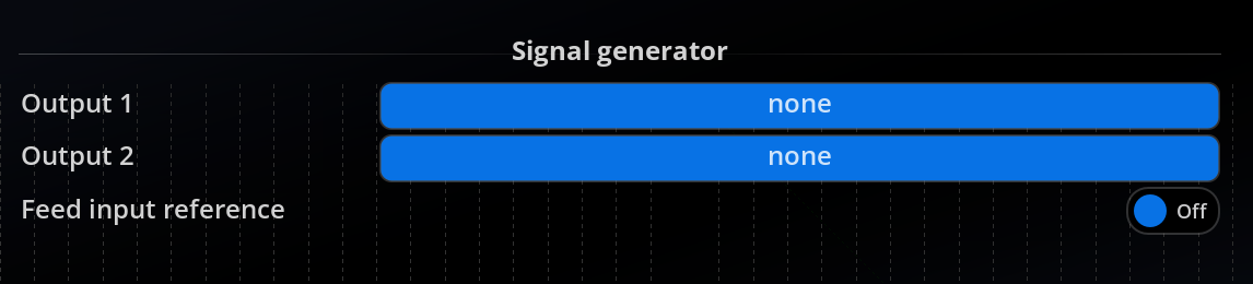
Selects one or two physical channels to which the Signal generator output should be sent.
In the case of dual output, the signal is identical on both channels. This is provided as a facility for sound cards with minimal routing capabilities, and to avoid using a Y patch cable.
Internal loopback
Best practices in terms of function transfer measurement advice include making a physical loop between an output and an input of the audio interface to feed the noise generator into the reference input of MiRA.
In many scenarios, it is much easier to create a “software” loop. This can be achieved by activating the “internal loopback” switch. The signal generator is then routed to the input channel matching the output channel. In other words, if output 1 of the audio interface is selected, the signal will be looped back to input 1. Note that the looped back signal replace the input signal of the input channel.
Beware that, while being a handy option, we recommend using a physical loop as often as possible. The main drawback of the “software” loopback is that the latency of the sound card skews the delay measurements.