Processing Effects
SPAT Revolution includes a suite of built-in audio processing effects derived from the FLUX:: Evo product line. These effects let you shape your audio directly within SPAT Revolution — adjusting tone, dynamics, phase, and transients — without needing to go back to your DAW or use external plug-ins.
Where are processing effects available?
Processing effects are available on three types of objects in your signal flow, each at a different stage:
- Sources — The full effect chain is available: Drive, Phase, EQ, Compressor, and Touch. These effects are applied before spatialization, meaning they shape the sound of each source before it is placed in the room. You can access them from the source’s Audio FX panel in the Source Properties inspector.
- Masters — An EQ and a compressor is available on each master bus. It is applied after spatialization but before output routing, giving you tone control over the mixed spatial output. You can access it from the master block in the Setup Page.
- Outputs — A per-channel EQ is available on each output. This means that in a multi-channel output (for example, a 7.1.4 system with 12 channels), each individual speaker channel gets its own independent EQ. This is applied after output routing, just before the final output. You can access it from the output block in the Setup Page.
Source Effect Chain
On a source, the five effects are processed in the order they appear in the FX list grid. The default order is:
Input Signal → Drive → Phase → EQ → Compressor → Touch → Spatialization
You can reorder the effects using the Move Up / Move Down buttons in the FX list grid to suit your needs. For example, you might want to place the Touch de-esser before the compressor, or move the Drive after the EQ.
Audio FX panel
The Audio FX panel is part of the Source Properties inspector. It consists of three areas side by side:
- FX list grid (left) — Lists all five effects with checkboxes to activate and bypass each one individually. Click an effect to select it and show its controls.
- Effect controls (center) — Displays the knobs, sliders, and parameters for the selected and active effect(s). If you select multiple effects, their controls are displayed side-by-side.
- Output meter (right) — Shows the output level after all effects have been applied.
Each effect panel can also be opened in a detached window for easier editing. The EQ, Compressor, and Touch effects all support this feature — look for the detach button in the panel header.
Global controls
Two global controls apply to the entire effect chain on a source:
- Activate Rack — A master on/off switch for the entire Audio FX rack. When turned off, all effects are disabled regardless of their individual activate states.
- Bypass Rack — Bypasses the whole rack while keeping all settings intact. Use this to compare the processed and unprocessed signal with a single click.
These rack controls do not erase individual effect settings. They sit above the per-effect Activate and Bypass switches in the grid, so you can temporarily disable the whole rack and return to the previous per-effect state later.
Drive
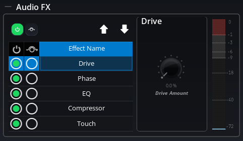
The Drive effect adds harmonic saturation and warmth to your audio signal. It has been specially designed to add a soft saturation that restores and maintains the vitality of the sound — similar to the analog warmth you would get from driving a signal into a console input stage.
The Drive is completely stateless, meaning it introduces no latency and has no memory of previous audio — it simply shapes each sample as it passes through.
Parameters
- Activate — Turns the Drive effect on or off.
- Bypass — Bypasses the Drive while keeping its settings.
- Drive Amount (0–100%) — Controls the intensity of the saturation. At 0%, no saturation is applied. As you increase the amount, the signal gains more harmonic content and warmth. Higher values produce a more noticeable saturation effect.
Phase
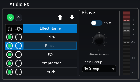
The Phase effect provides a linear phase rotation throughout the spectrum, allowing you to correct phase issues between multiple microphones — for example, when recording a drum kit with several microphones at different distances. This is the same zero-latency phase correction technology found in the FLUX:: Evo Channel plug-in.
In practice, this works the same way as physically moving a microphone: it shifts the phase of the signal without adding any latency, giving you precise control over how multiple sources interact when combined.
Phase groups
Sources can be assigned to a Phase Group (1–8) to link their phase switching. When you toggle the Phase on or off for any source in a group, all other sources in the same group are toggled as well.
This is very useful for multi-microphone setups: activate the phase module on all the tracks that were recorded at the same time and in the same room, assign them to the same group, and then use the phase amount slider on each track to find the optimal phase alignment. You can then enable or disable phase correction for all of them with a single click.
Setting the Phase Group to 0 means “no group” — the source’s phase toggle will operate independently.
Parameters
- Activate — Turns the Phase effect on or off.
- Bypass — Bypasses the Phase while keeping its settings.
- Shift On — Enables or disables the phase correction. This is the toggle that propagates across phase groups.
- Phase Amount (−180° to +180°) — Sets the phase rotation angle. Adjust this value until the combined signal from multiple microphones sounds correct.
- Phase Group (0–8) — Assigns the source to a phase group for linked operation.
EQ
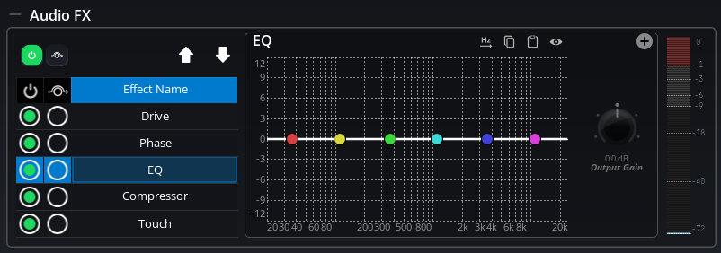
The EQ is a comprehensive parametric equalizer with up to 16 bands. The graphical interactive EQ curve is layered on top of a built-in spectrum analyzer, giving you hands-on editing with a direct visual connection to the frequency response.
Available filter types
Each band can be set to one of the following filter types:
| Filter Type | Description |
|---|---|
| Low Pass | A smooth low-pass filter with a maximally flat Butterworth passband response |
| High Pass | A smooth high-pass filter with a maximally flat Butterworth passband response |
| Band Pass | Passes only a specific frequency range with smooth Butterworth characteristics |
| Band Stop | Rejects a specific frequency range (the opposite of band pass) |
| Low Shelf | A shelving filter using Butterworth design for a smoother transition |
| High Shelf | A shelving filter using Butterworth design for a smoother transition |
| Band Shelf | A band shelving filter using Butterworth design |
Per-band parameters
Each of the 16 bands has the following parameters:
- Band Enable — Turns the band on or off.
- Band Type — Selects the filter type from the table above.
- Band Slope — Sets the steepness of the filter curve (filter order).
- Band Cutoff (Hz) — Sets the center or cutoff frequency of the band.
- Band Gain (dB) — Sets the amount of boost or cut. Only used for shelving and peak filter types.
- Band Resonance — Controls the resonance (Q factor) of the filter.
- Band Bandwidth (Octaves) — Sets the width of the affected frequency range.
EQ display range
The EQ curve display range can be set to Auto or a fixed dB range, depending on how much detail you need to see.
Copy and Paste EQ
The EQ dialog includes Copy and Paste buttons that let you transfer EQ curves between any EQ in SPAT Revolution — or between SPAT Revolution and MiRA Analyzer.
- Copy — Serializes the current EQ settings (all band parameters) to the system clipboard.
- Paste — Reads an EQ configuration from the system clipboard and applies it to the current EQ.
Since SPAT Revolution and MiRA share the same EQ engine, the clipboard format is fully compatible between both applications. This enables a powerful system tuning workflow: measure your room or PA system in MiRA, design corrective EQ curves (manually or using MiRA’s Auto-EQ feature), then copy and paste them directly into SPAT Revolution’s Output or Master EQ. See the MiRA EQ integration workflow for step-by-step instructions.
Detached EQ window
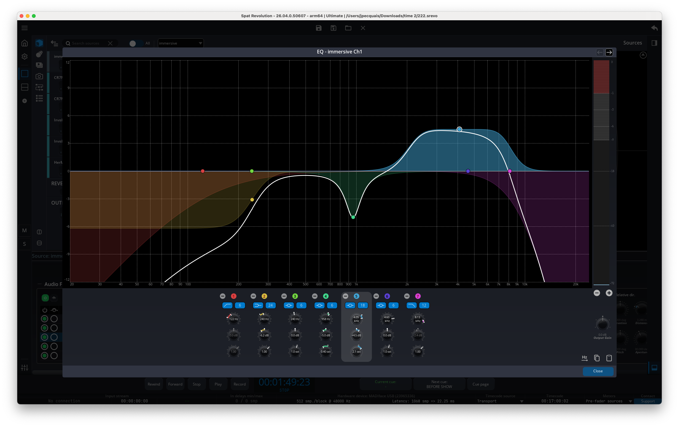
The EQ panel can be opened in a detached window — a resizable, standalone window that displays the full EQ curve and controls. This is very useful when you need more screen space to fine-tune your EQ settings.
Compressor
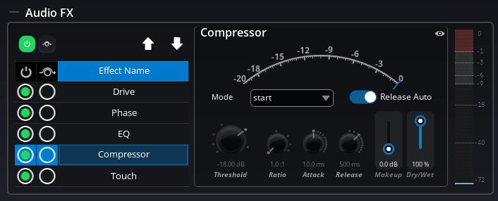
The Compressor is a full-featured dynamics processor based on the FLUX:: Evo Compressor engine. In addition to controlling the signal dynamics, it can be used creatively for shaping the attitude and character of a sound. It provides a gain reduction meter so you can always see how much compression is being applied.
Mode presets
To make it easy to get started, the compressor offers 9 mode presets that configure all parameters at once for common use cases. Simply select a mode and the threshold, ratio, attack, release, and knee values are automatically set to appropriate starting points.
| Mode | Best for |
|---|---|
| Start | Neutral starting point (default) |
| Kick/Snare | Percussive sources like kick and snare drums |
| Overhead | Drum overhead microphones |
| Drum Bus | Gluing a drum bus together |
| Bass | Bass instruments |
| Acoustic | Acoustic instruments |
| Piano | Controlling piano dynamics |
| Vocal | Vocal compression |
| Mix | Mix bus compression |
These presets are great starting points — once selected, you can fine-tune any parameter to taste.
Parameters
- Activate — Turns the Compressor on or off.
- Bypass — Bypasses the Compressor while keeping its settings.
- Mode — Selects a compression preset (see table above).
- Threshold (−60 to 0 dB) — The level above which compression begins. Signals below the threshold pass through unaffected.
- Ratio (1:1 to 10:1) — How much the signal is reduced once it exceeds the threshold. A ratio of 1:1 means no compression. A ratio of 4:1 means a signal that exceeds the threshold by 4 dB will be reduced to only 1 dB above it.
- Attack (0.1–1,000 ms) — How quickly the compressor reacts when the signal exceeds the threshold. Short attack times catch fast transients; longer times let transients through.
- Release (1–10,000 ms) — How quickly the compressor stops compressing after the signal drops below the threshold.
- Auto Release — When enabled, the compressor automatically adapts its release time to the input signal, producing more natural-sounding compression. The release time value acts as a maximum limit.
- Makeup Gain (0–24 dB) — Boosts the output level to compensate for the gain reduction caused by compression.
- Wet (0–100%) — Controls the mix between the compressed signal and the original (dry) signal. At 100%, you hear only the compressed signal. Lower values allow for parallel compression — blending the compressed and uncompressed signals for a more natural result.
Gain Reduction Meter
The compressor displays a gain reduction meter ranging from −20 dB to 0 dB, where 0 dB means no reduction is occurring.
Advanced parameters (Geek Panel)
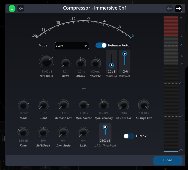
For users who need deeper control, the Compressor provides an advanced panel (accessed via the “Geek” button) with additional parameters:
- Detection Mode — Selects the compression algorithm. The default is Classic Feedback Slow, which is inspired by vintage hardware architectures and creates a naturally beefy sound with a sort of auto-regulation. Ten modes are available, ranging from Solera (FLUX:: proprietary) to various Classic and Classic Feedback modes with different detection speeds (Fast, Medium, Slow, Extra Slow).
The Feedback modes analyze the compressor’s output signal rather than the input, creating a self-regulating behavior inspired by vintage compressor designs.
- Peak/RMS (0–100%) — Blends between peak and RMS detection. At 0%, the compressor responds to average signal levels (RMS). Increasing this value adds peak detection, making the compressor more sensitive to transients.
- Knee (0–24 dB) — Controls the smoothness of the compression curve around the threshold. A knee of 0 dB produces a hard knee (abrupt transition), while higher values create a softer, more gradual compression onset.
- Dynamic Factor — Amplifies or dims the extracted real-time dynamic information.
- Dynamic Velocity — Sets the speed of variation on the dynamic information.
- Dynamic Ratio (0–100%) — Relaxes the compression ratio based on the signal’s dynamic range. Higher values open up the sound, increase the dynamic impression, and keep transients intact. This is especially effective on drum buses or full mixes.
- L.I.D. (Level Independent Detector, 0–100%) — Processes the signal based on its dynamic range independently of the overall level. This allows the compressor to work consistently regardless of whether the signal is loud or quiet — very useful when dealing with material that has large level variations.
- L.I.D. Threshold (0–24 dB) — Sets the gain range of the L.I.D. parameter.
- H.Max — When enabled, the threshold is determined by the maximum of the RMS/peak detection or the dynamic detection, making the compressor more reactive to signal content.
- SC Low Cut (20–20,000 Hz) — Filters low frequencies out of the sidechain detection circuit. Useful for preventing bass-heavy content from triggering excessive compression.
- SC High Cut (20–20,000 Hz) — Filters high frequencies out of the sidechain detection circuit.
- Release Min (0.1–5,000 ms) — Sets the minimum release value when Auto Release is enabled.
- Hold (0–500 ms) — Holds the compression for a specified time before the release phase begins. Useful for precise gating effects, especially on drum tracks.
Touch
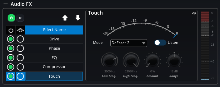
The Touch effect is a polymorphic processing module based on the FLUX:: Evo Touch engine. It adapts to the requirements of your material by offering seven different processing modes, including transient and sustain shaping, de-essing, and frequency-band expansion. Different types of material require different tools — whether it’s a vocal, drums, guitar, piano, or something else — and Touch provides the right processor for each situation.
Like the Compressor, Touch displays a gain reduction meter so you can monitor the processing in real time.
Processing modes
Touch offers seven modes, each designed for a specific task:
- Transient Boost — Enhances the attack transients of the sound. Great for adding punch to drums or making plucked instruments more articulate.
- Transient Kill — Suppresses transients. Useful for softening percussive sounds or reducing pick noise on guitars.
- Sustain Boost — Enhances the sustain portion of the sound. This can add body and presence to instruments.
- Sustain Kill — Suppresses the sustain, leaving mainly the transient attack. Creates a more staccato, percussive character.
- DeEsser 1 — A gentle de-esser that tames sibilance on vocals with a smooth, transparent approach.
- DeEsser 2 — A more aggressive de-esser with a steeper filter slope, for vocals with pronounced sibilance. This is the default mode.
- Expander — A frequency-band expander that reduces the level of signals within a specific frequency range when they fall below a threshold.
When you select a mode, the advanced parameters are automatically adjusted to match the mode’s optimal defaults.
Parameters
- Activate — Turns the Touch effect on or off.
- Bypass — Bypasses the Touch while keeping its settings.
- Mode — Selects the processing mode (see above).
- Low Freq (20 Hz – Nyquist) — Sets the lower bound of the frequency range the Touch module works on. Default is 3,900 Hz.
- High Freq (20 Hz – Nyquist) — Sets the upper bound of the frequency range. Default is the Nyquist frequency (half the sample rate).
- Listen — When enabled, you can monitor the signal within the defined frequency range in isolation. This helps you set up the frequency range accurately.
- Amount (0–100%) — Controls the intensity of the processing. Default is 0% (no processing).
- Range (0–24 dB) — For de-esser modes, this limits the maximum gain reduction. For transient/sustain modes, this controls the processing depth. Default is 12 dB.
The Low Freq and High Freq values are edited with a double slider: the lower handle sets the bottom of the active band and the upper handle sets the top. This makes the selected frequency window visible as one range instead of two unrelated values. Drag either handle to narrow or widen the band, or edit the numerical values when you need an exact cutoff.
The High Frequency must be at least one octave above the Low Frequency (High Freq ≥ Low Freq × 2).
Advanced parameters (Geek Panel)
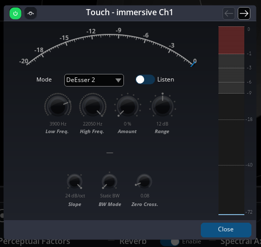
Additional controls are available in the advanced panel:
- Release (1–1,000 ms) — Sets the release time for the transient processing envelope. Default is 20 ms.
- Bandwidth — Controls the Q factor behavior:
Static BWprovides a constant Q factor,Dynamic BWadapts the Q factor based on the filter gain, andFlat Sumuses a traditional Q computation. - ZCR Threshold — The Zero Crossing Rate threshold, which helps the processor detect transients. This is automatically set when selecting a mode.
- Slope (6/12/18/24 dB/oct) — Sets the steepness of the frequency-dependent filtering. Higher values create a steeper, more focused filter response.
Master EQ
Each Master block (room output bus) includes a parametric EQ. It is identical to the source EQ described above — up to 16 bands with the same filter types — but it operates after spatialization, giving you tone control over the mixed spatial output before it reaches the output stage.
The Master EQ is accessible directly from the master block in the Setup Page:
- An Activate switch lets you toggle the EQ on or off.
- An Edit button opens the EQ in a detached window for full curve editing.
The Master EQ is separate from the source effects and has its own dedicated controls in the master block. It does not appear in the Source Properties panel.
Output EQ
Each Output block includes a per-channel EQ. Unlike the source and master EQs, which process the entire bus, the output EQ creates an independent EQ for each individual output channel. This allows you to apply different EQ curves to individual speakers in a multi-channel output.
For example, in a 7.1.4 output (12 channels), each of the 12 speaker channels gets its own independent 16-band parametric EQ. This is useful for compensating for room acoustics or speaker response differences on a per-speaker basis.
The Output EQ is accessible from the output block properties in the Setup Page, and supports the same detached window editing as the Master EQ.
In the detached Output EQ window, use the channel selector or previous/next controls to choose which output channel you are editing. The title-bar Activate and Bypass switches apply to the selected channel. Shift-click those switches to apply the same activate or bypass state to all channels of the output.
The Output EQ is the ideal destination for system tuning corrections from MiRA Analyzer. After measuring each speaker in your system with MiRA, you can copy the corrective EQ curve and paste it into the corresponding output channel’s EQ in SPAT Revolution. This gives you per-speaker room correction directly within your spatialization workflow.
Integration with Snapshots and Cues
All processing effect parameters are fully integrated with the SPAT Revolution snapshot and cue systems:
- Snapshots capture and recall all Audio FX parameter values. When you recall a snapshot, your effect settings (EQ curves, compressor thresholds, drive amounts, etc.) are restored along with all other source and room parameters. Effect parameters can also be smoothly interpolated during snapshot morphing.
- Cue actions can target Audio FX parameters — both through Snapshot Recall actions and through Object Action actions that directly control specific effect parameters.
- All effect parameters are saved in session files and can be included in presets.
Animations and LFOs cannot currently target Audio FX parameters. Only spatial and position parameters are available as animation targets.
OSC Remote Control
All processing effect parameters can be controlled remotely via OSC. The standard SPAT Revolution OSC addressing patterns are used:
| Object Type | OSC Pattern |
|---|---|
| Source | /source/[remote_number]/<property_name> |
| Master | /master/[remote_number]/<property_name> |
| Output | /output/[remote_number]/<property_name> |
Here are some examples:
/source/1/DriveAmount 50.0— Set the drive amount on Source 1 to 50%/source/1/CompressorThreshold -24.0— Set the compressor threshold on Source 1 to −24 dB/source/1/TouchMode 0— Set the Touch mode on Source 1 to Transient Boost/source/1/PhaseAmount 90.0— Set the phase shift on Source 1 to 90°/source/1/CompressorGlobalMode 7— Select the “Vocal” compressor preset on Source 1/master/1/EQActivate 1— Enable the EQ on Master 1/output/1/EQBandCutoff 0 1000.0— Set Output 1’s EQ band 0 cutoff frequency to 1 kHz
All effect parameters support both get and set operations via OSC. For the complete list of available OSC messages, see Appendix D — Appendix C - OSC Table.